Know what the light will do before the truck rolls.
Throwcast is a 3D planning studio for projection rigs: model the venue, place projectors and devices with real optics, connect them with cable — and print the paperwork the crew rigs from.
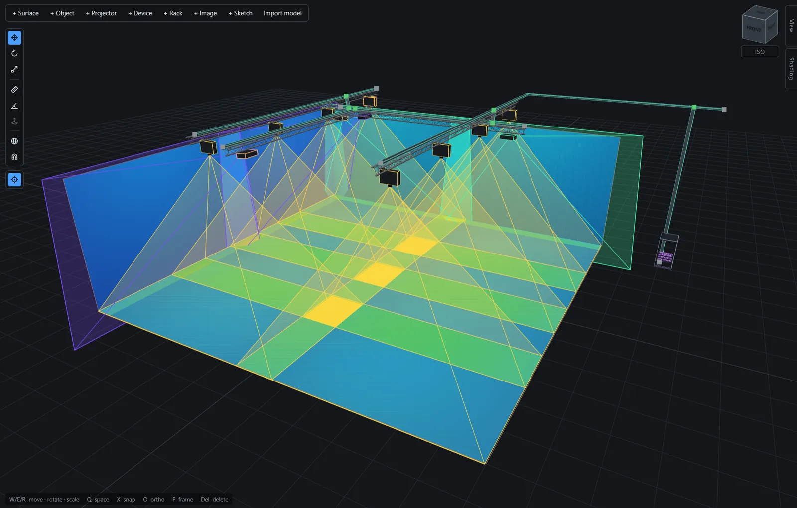
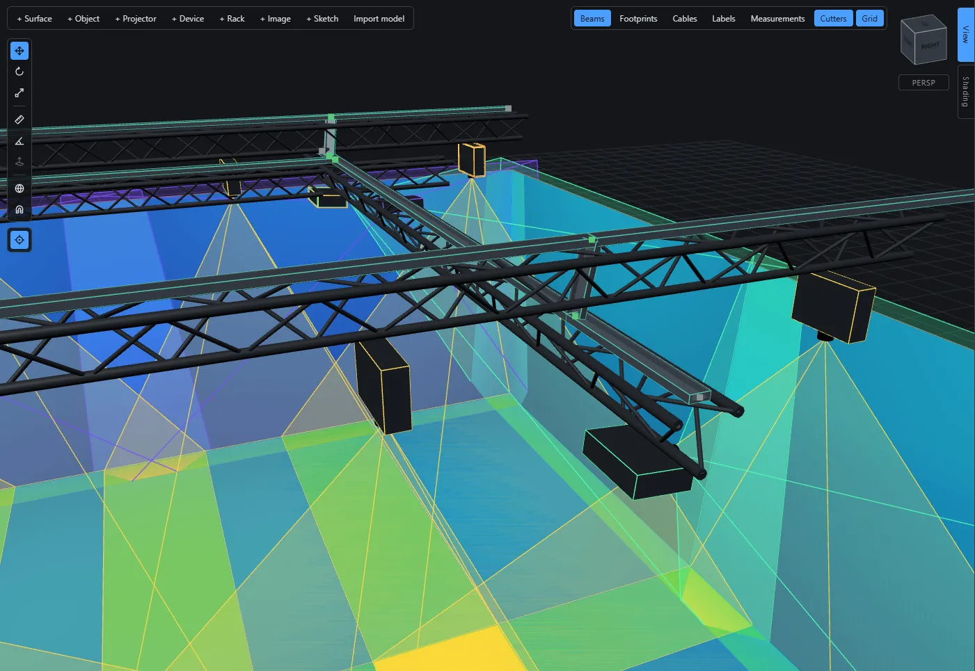
- Projectors on truss. Real bodies, real lenses, frustums drawn from the optics rather than sketched.
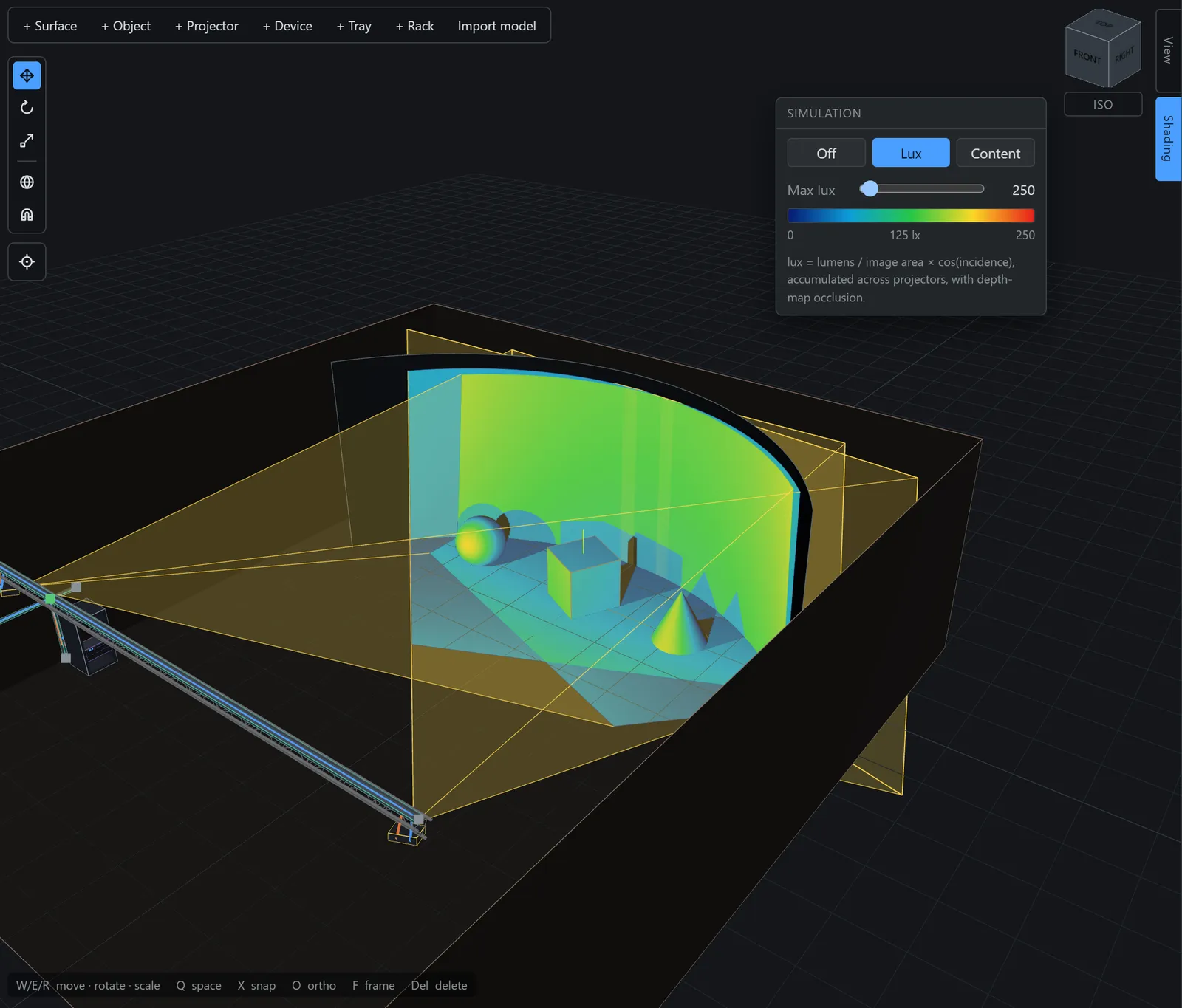
- Lux accumulates. Where two beams overlap the floor reads hotter, through a false-colour scale you set.
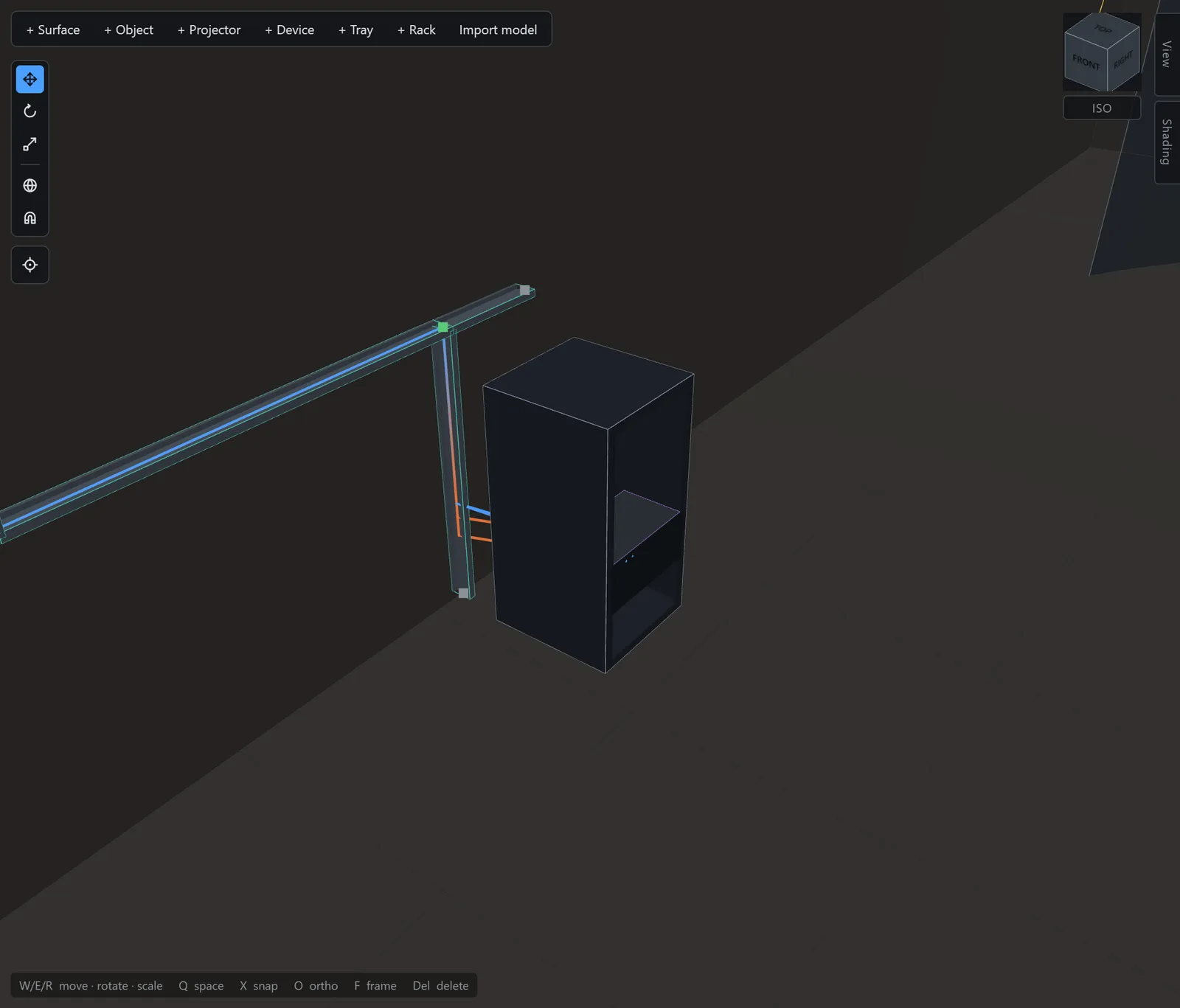
- Tray runs. Place cable trays in 3D and assign a cable to the network — it routes itself along the shortest path, and the length is computed for you.
- Rack. Devices mounted into units, wired, and printable as a front elevation.
Built for the people who plan the rig
Four trades put projection on paper. Throwcast is for whoever’s name is on that paperwork.
- Projection installation designers
- Prove the install before anything is bought. Model the room, place the machines, and show coverage, lux and pixel density against the real geometry — with documentation the client and the consultant can check.
- Mapping show designers
- Model the façade, the set or the dome, design the blend array on it, and preview your content on the surface it will actually hit — the canvas is settled before the first truck is packed.
- Rental & staging companies
- The equipment list and the cable schedule fall straight out of the model: a pull sheet you can pack a truck from, with cable lengths taken from routed runs rather than a walk of the venue.
- System integrators
- The whole system in one document — optics, racks, signal flow. Rack elevations, patch diagrams and schedules print from the same model the design was made in, so nothing is kept in sync by hand.
Model the venue in place
Floor plan → trace → extrude → cut, inside the tool. Every surface is a projection target and an occluder from the moment it exists — and nobody needs a CAD seat before the room can be planned.
-
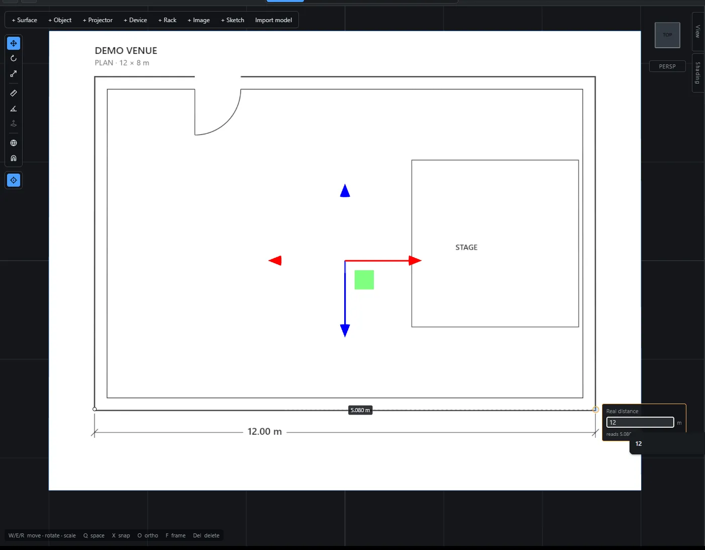
Start from the architect’s plan
Drop a floor plan or elevation into the venue — on the ground, on a wall, on any face. Measure one known distance across it and the whole drawing scales to life. It’s a drafting aid, not a screen: never lit, never an occluder, but always there to dimension against.
-
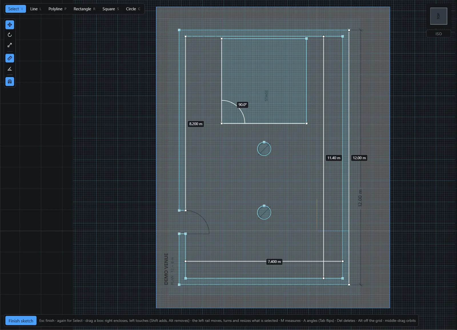
Trace it on any plane
Sketch lines, rectangles and circles straight onto the plan, with dimensions typed mid-gesture. Corners and closed regions are derived rather than stored, so coincident ends simply are one corner, and a circle inside a rectangle is both the bored plate and the disc.
-
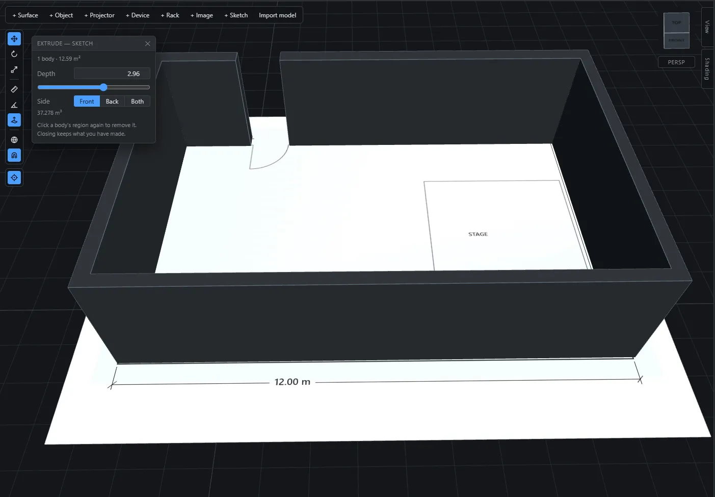
Then push it into a solid
Extrude a closed outline and the body stays live-linked to the drawing: move a wall in the sketch and the geometry follows. The riser with a notch, the set wall in plan, the room itself — shapes no primitive can make.
-
Add surfaces, whatever shape the screen is
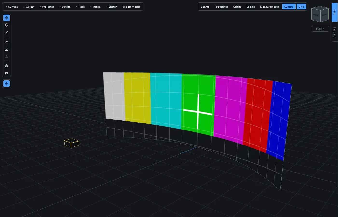
Flat, curved, a closed 360° cylinder, or a dome — one object with a shape field you can change at any time, so a wall that turns out to be a cyc keeps its position, its name and every annotation pinned to it. A dome is placed by its centre of curvature, where the audience sits, and asks for the two numbers the trade quotes: radius and dome angle.
-
Add trusses, set and geometry
Bring in GLTF, OBJ or FBX — the venue shell, trusses, set pieces — with a unit and up-axis dialog on the way in and materials preserved. Big CAD stays quick to pick and measure, and every mesh is a projection target and an occluder the moment it lands.
-
Cut the doorway where the doorway is
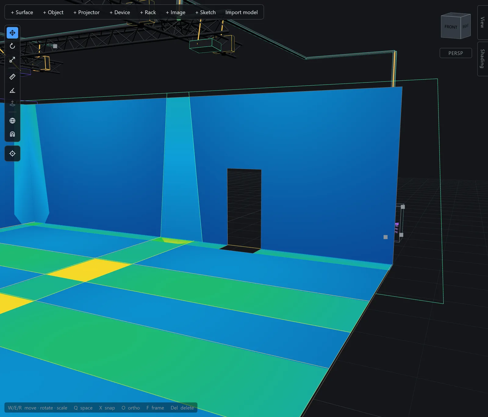
A cut is a body you place, not a field on a wall. Push a box through the wall and you have a doorway; drag it and the doorway moves, hide it and the wall closes up. One cutter opens everything it touches, so in a corner it opens both walls at once — and light, shadow, the probe and your clicks all pass through the opening.
Place the rig, then light it
Projectors with validated optics, devices with real ports, racks with real units — connected by cable that routes itself, and simulated as light before the load-in.
-
Place projectors with real optics
Throw ratio, lens shift, aspect — validated against a shipped 30-projector production. Place machines from two bundled vendor catalogues, 177 bodies and 248 lenses from Epson and Panasonic, or define your own; a blend array clones one projector into a grid and stays editable for the life of the project.
-
See the light before the load-in
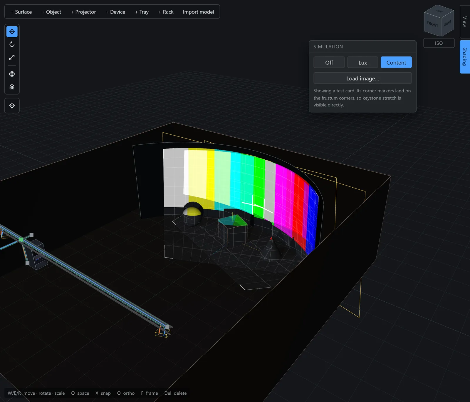
A lux heatmap and a content preview, occlusion-aware, with no baking — up to 32 projectors at once. Where beams overlap the surface reads hotter, through a false-colour scale you set, and the hover probe reads lux and px/m at any point, per projector.
-
Add the rest of the machines
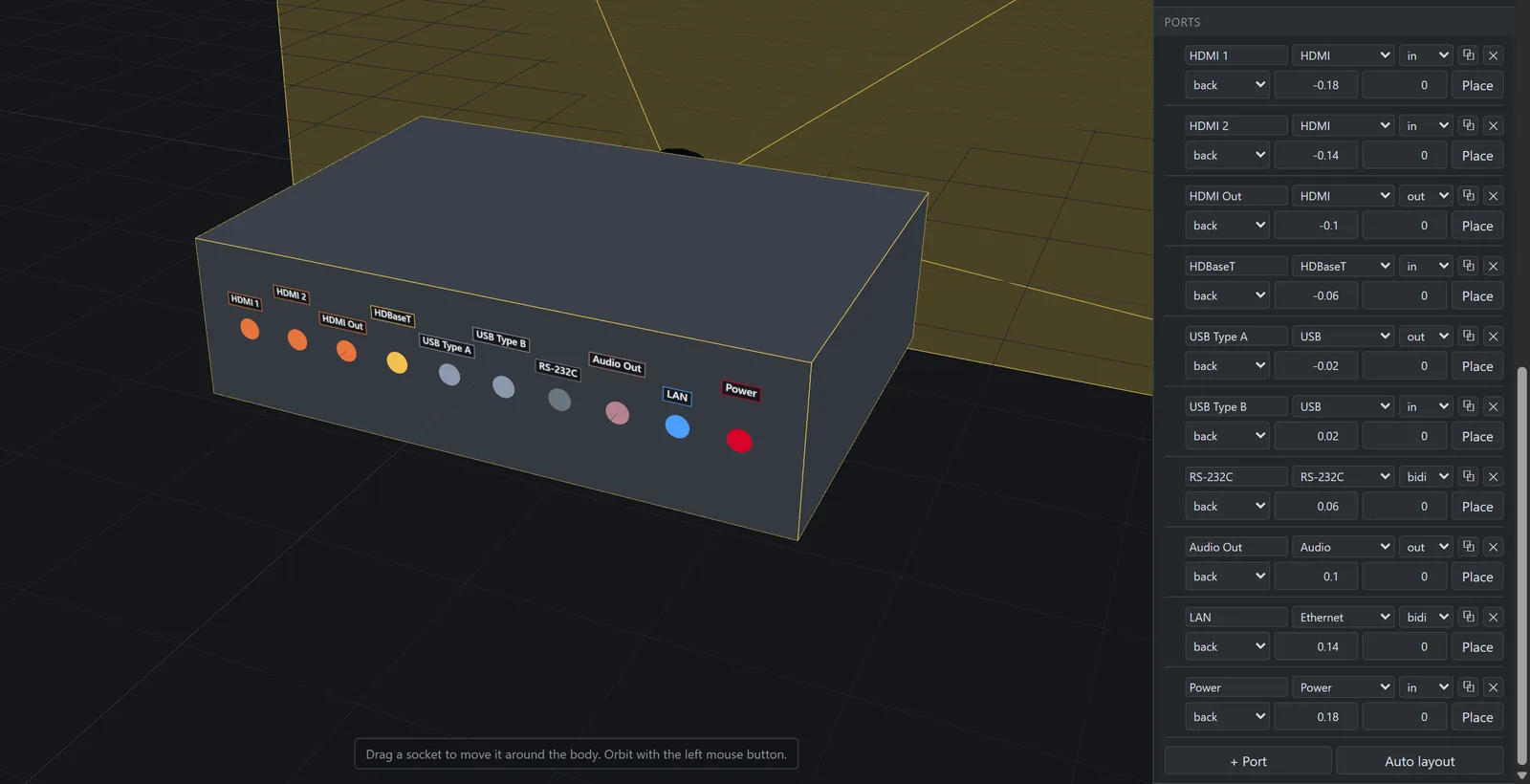
Media servers, splitters, switchers — every device is a real body with typed ports on the faces they actually sit on. Duplicate a port and it keeps its type and direction, numbered the way a back panel is; a cable lands on the socket, not on the middle of the box.
-
Mount them in racks
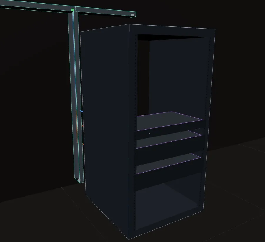
A rack is an enclosure with real units. Rackmount devices mount into it, loose boxes sit on shelves, and fit is enforced — a row has to fit the plate, and under whatever is above it. The front panel is part of the device, so a front port lands on the panel where the sockets really are.
-
Connect with cables
Run cable trays through the venue, then assign a cable to the network and it routes itself along the shortest path through the trays — lengths come from the routed 3D run plus slack, not from a guess. Joints are derived from the geometry itself: nothing to link up, nothing to go stale when you edit.
-
The same rig as a schematic
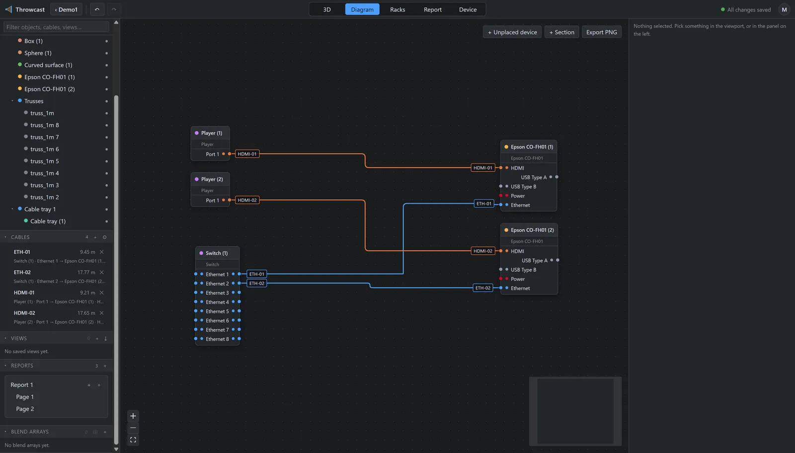
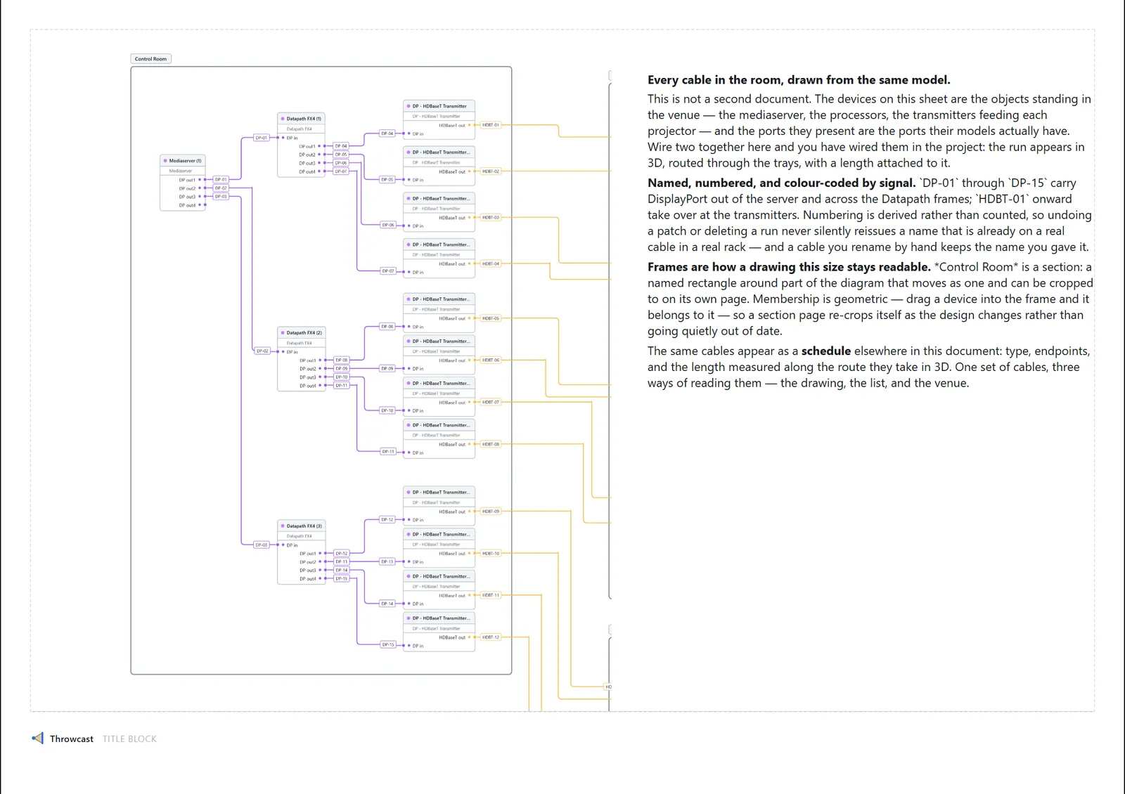
A 2D signal diagram, fully driven by the document: device nodes, typed ports, colored cable runs. Drag port to port to patch; the FOH rack nobody modelled lives here too.
-
Describe machines of your own
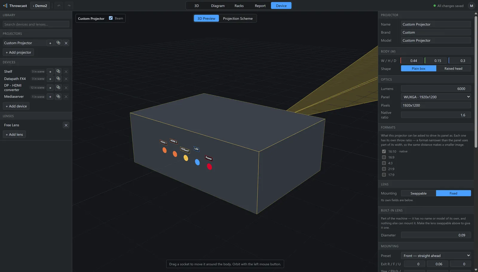
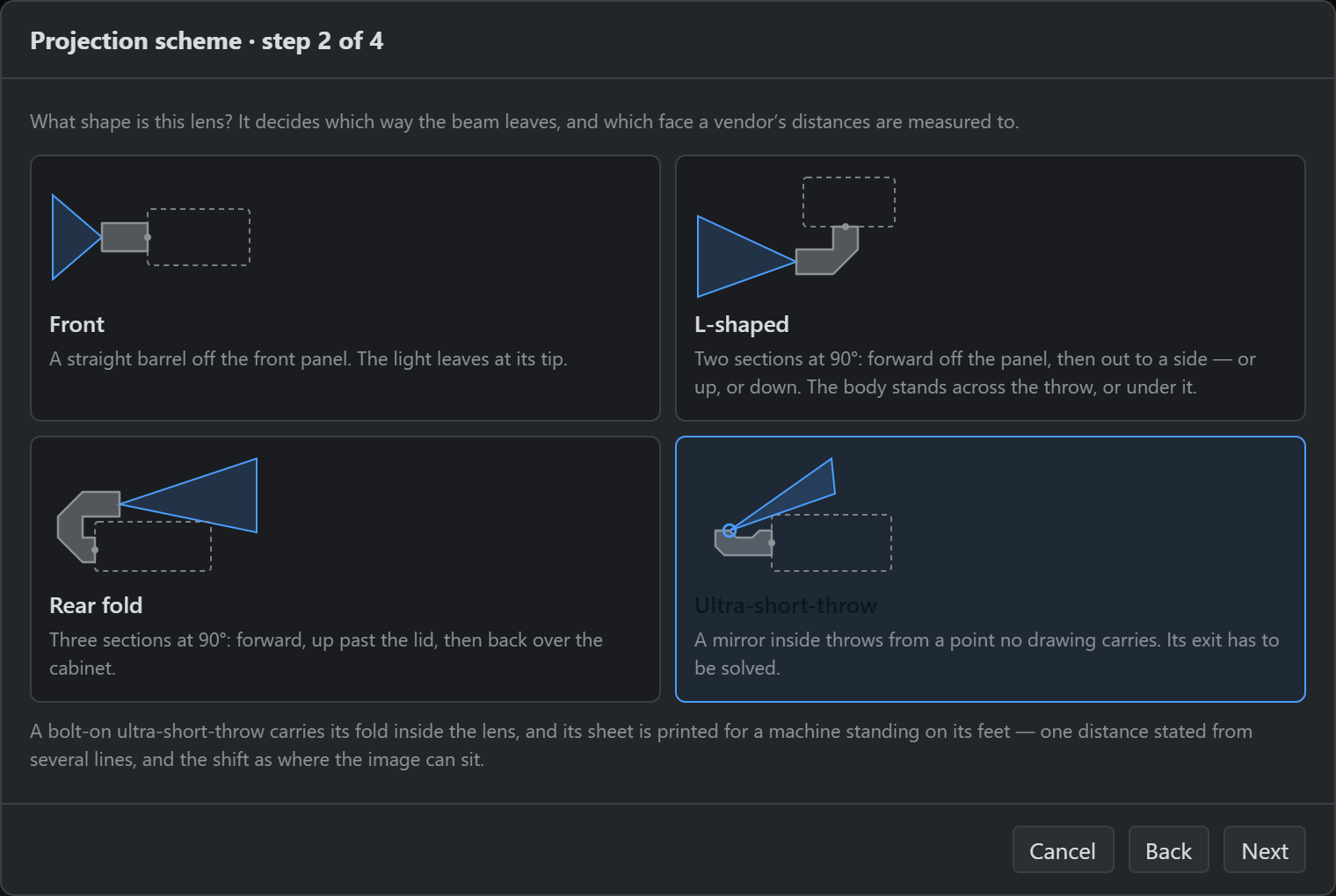
The Device tab is a library workshop: definitions with 3D bodies, port panels, lenses and per-format throw ratios drive every instance in the scene — edit the machine once and the whole rig follows. A four-step wizard turns the vendor’s printed table into a working projector, solving the throw scheme live as you type.
-
Lenses that draw honestly
Fixed or swappable, with per-format throw ratios and shift travel. A folded path is drawn as it really sits: an ultra-short-throw throws from a virtual point no distance along forward can reach, a right-angle lens turns the beam through an internal mirror, a rear-throwing lens folds the path back over the cabinet.
Paper the crew can rig from
A report page is a sheet you arrange blocks on — 3D views, text, cable and equipment schedules, rack elevations, diagram slices, blend-array tables. Drag, resize, snap, duplicate, then export the set as a multi-page PDF at 150 or 300 dpi.
-
A sheet you arrange blocks on
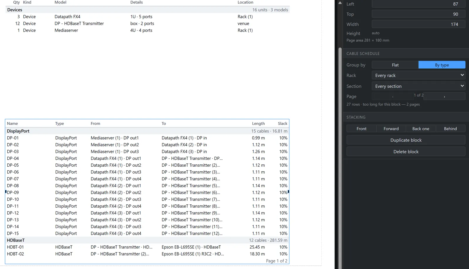
Drag, resize, snap and duplicate blocks — 3D views, text, schedules, diagram slices — the way you would lay out a drawing sheet. A table longer than its paper paginates onto the next sheet, and the set exports as a multi-page PDF at 150 or 300 dpi.
-
3D views that stay true
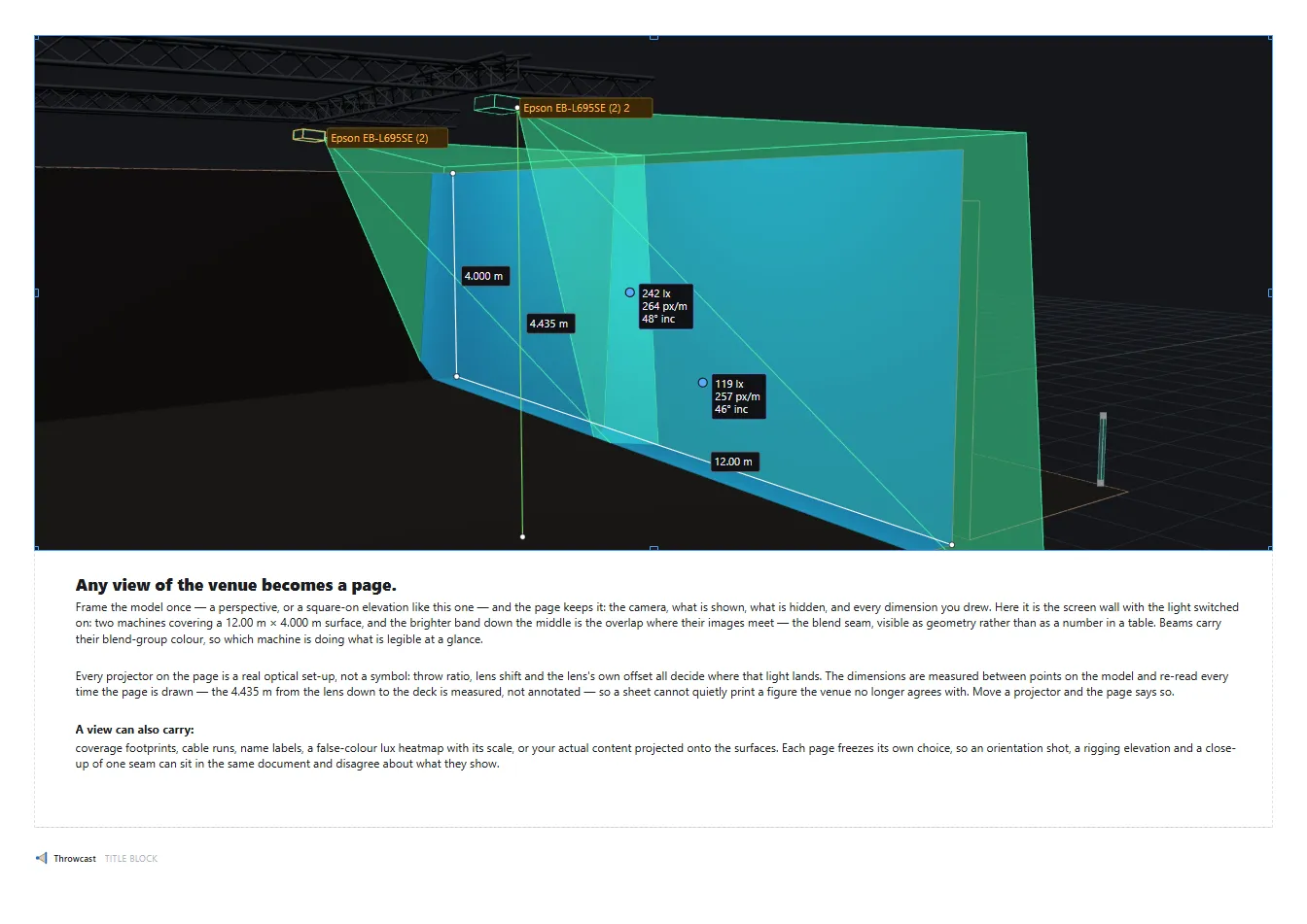
A view block carries its own camera, hidden set and annotations — including lux and px-per-m pins that recompute, so the numbers on the sheet stay true as the rig changes. Every block reads the project, not a snapshot of it.
-
Slices of the signal diagram
Drop the patch onto the sheet and crop it to the section that matters, so the page carrying the FOH rack shows the FOH rack rather than the whole plant. Sections are geometric, so a device joins one by being dragged inside it.
-
Rack elevations
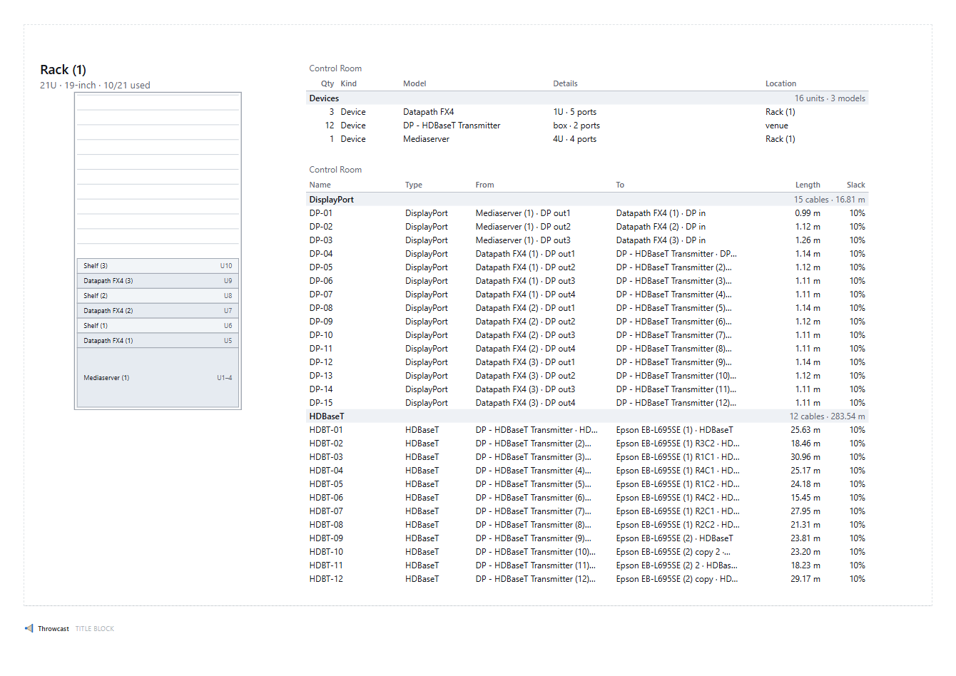
The front of every rack, drawn as vectors and contain-fitted to its block — what is mounted where, in units, exactly as the build crew will stand it up.
-
Cable and equipment lists
Schedules are derived the moment the page is drawn, so they cannot go stale.
- Cable schedule with lengths from real routed 3D polylines and slack %; a run with an unplaced end reads “unplaced”, never 0.00 m
- Equipment list grouped by machine and location — two of the same switcher in two racks are two rows, because the list is for building a rack as well as buying the kit
-
Or the same rig as a technical drawing
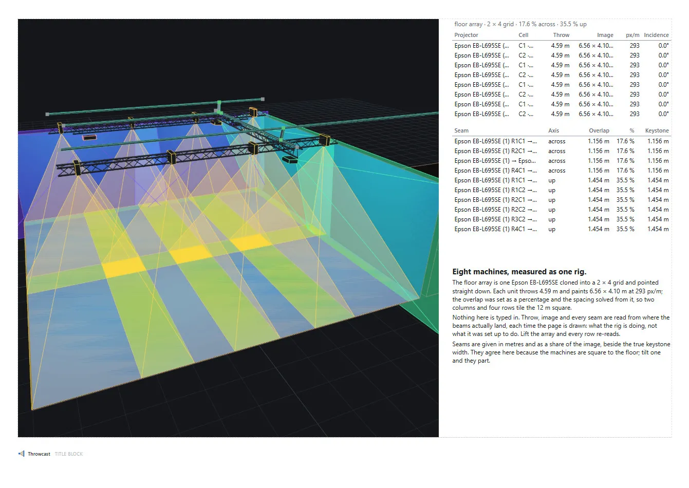
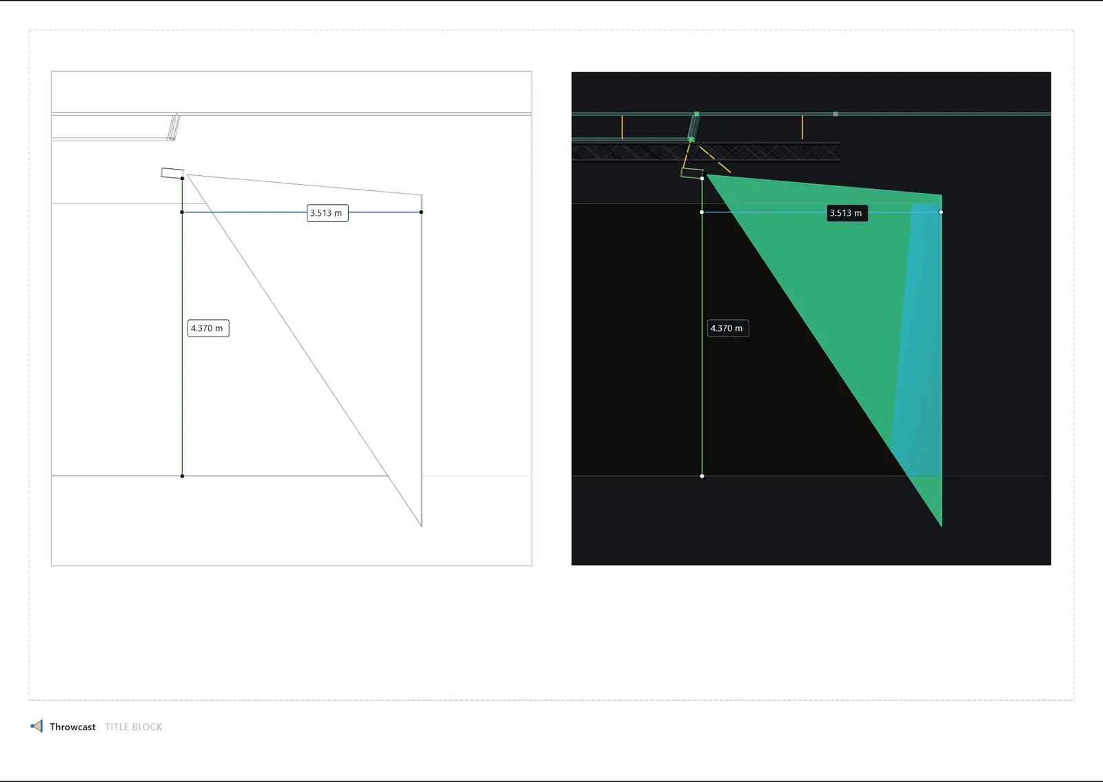
A view block can render black edges on white paper instead of the lit venue — hidden lines removed, the grid pale as construction lines. One page can carry the shaded render and the line drawing of the same rig side by side, with vertex-snapped measurements and one generated throw-diagram page per projector, drawn as vectors.
Specifications
What the studio does, in the units the job is measured in. Counts and limits of the product itself; the optics behind them are asserted by the test suite against a shipped 30-projector production.
Venue
| Model import | GLTF · OBJ · FBX | Unit and up-axis dialog on the way in, materials kept, fast picking on large CAD |
|---|---|---|
| Reference images | any image | A plan or elevation on the floor, a wall or any face, scaled to life from one measured distance |
| Sketch and extrude | 5 tools | Line, polyline, rectangle, square, circle, dimensions typed as you draw; a closed region pushes into a solid that follows the drawing |
| Projection surfaces | 4 shapes | Flat, curved arc, closed cylinder, dome; rear projection per surface |
| Objects and cutters | 5 solids · 4 cutters | Room, box, cone, cylinder, sphere, plus box and triangle truss; a cutter opens whatever it touches |
| Measuring | distance · angle | Between points on the model, in the venue, on a page or in a sketch, re-read every time the page is drawn |
Optics
| Simultaneous projectors, real time | 32 | Per-fragment lux heatmap and content preview, occlusion-aware, no baking |
|---|---|---|
| Lens paths | 4 kinds | Front, right-angle, rear fold, ultra-short-throw, each drawn from where its light really leaves |
| Readouts | throw · image · px/m · lux | Per projector and under the cursor, live as the rig moves |
| Blend arrays | grid · ring | Spaced by overlap % or by metres; every seam read in metres and as a share of the image, planar and true keystone |
Devices
| Projector catalogue | 177 bodies · 248 lenses | Epson and Panasonic, read-only; importing copies into your project, or define your own from the vendor’s printed table |
|---|---|---|
| Port types | built-in · custom | HDMI, DisplayPort, SDI, HDBaseT, fibre, Ethernet, DMX, audio, USB, power and more, plus your own per project |
| Racks | 19-inch | Real units and shelves, fit enforced; front elevations drawn as vectors |
| Cables | trays · diagram | Routed along the shortest path through the tray network, lengths from the routed run plus slack; a 2D signal diagram patched port to port |
Deliverables
| Report blocks | 7 kinds | 3D view, diagram slice, rack elevation, cable schedule, equipment list, blend-array table, text; long tables paginate |
|---|---|---|
| Paper and PDF | A4 · A3 · Letter | Portrait or landscape, multi-page, 150 or 300 dpi; drawings and elevations as vectors |
| Viewpoint export | up to 3840 px | Any saved view as a chrome-free PNG |
Platform
| Runs | in the browser | Nothing to install; the project autosaves to the cloud, and every account opens on a worked demo venue |
|---|
Early access is by invite
Throwcast is opening in early access. Join the list and we’ll email you when there’s a place. Every account opens on a worked demo venue — twelve projectors in three blend arrays, truss, a wired rack and a seven-page report — rather than an empty grid.
Invite-only while the beta is small. Your address is used to send the invite and for nothing else — privacy notice.
A projection planning studio for the people who rig it: optics, venue geometry, cables and the printable paperwork, carried in one document.